


Industrial Motor Drives & Protection
Measure harmonics on the supply side of variable-frequency drives. Review motor protection separately for direct-on-line and drive-fed circuits.
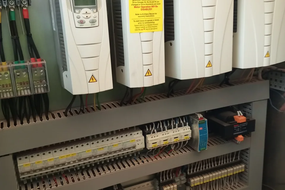
Drive feeder measurement and motor protection
Consider a factory motor control center that serves variable-frequency drives for pumps and fans alongside separately started auxiliary motors. The single-line diagram identifies the incoming supply, the drive input feeders and the direct-on-line motor circuits for separate review.
Measure the AC supply to the drives
Compare the drive feeder with the upstream bus during representative production cycles. Record voltage, current and the harmonic spectrum alongside motor speeds, load conditions and reactive power.
Assess filtering and compensation separately
If measured harmonic current exceeds the project target, evaluate an active harmonic filter on the supply side using the measured spectrum and existing input reactors or filters. Assess an SVG separately if the measurements show changing fundamental reactive power demand.
Review motor protection by starting method
For a direct-on-line motor circuit, review the SCBR2M against the motor nameplate, starting conditions and required control interfaces. For drive-fed motors, check the drive and motor documentation for thermal protection and compatibility of any output-side device.
Verify feeder harmonics and motor protection
Compare harmonic current and voltage distortion before and after mitigation at the same AC-side measurement point, with comparable motor speeds, loads and supply configuration. If IEEE 519 is specified, assess the agreed point of common coupling. Verify motor alarms and protection functions separately against the approved commissioning plan.
Prepare a project enquiry
- Single-line diagram showing the incoming supply, drive feeders and motor starters
- Drive models, motor nameplates and representative speed and load conditions
- Available harmonic and reactive power measurements, existing equipment and project targets