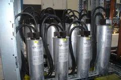


SUCYC-DB Detuned Capacitor Module
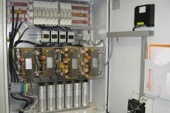
A factory-prewired reactive power compensation step combining a self-healing capacitor, series detuned reactor and thyristor or hybrid switch. Each module delivers 15–30 kvar on a three-phase 400 V system, depending on the model.
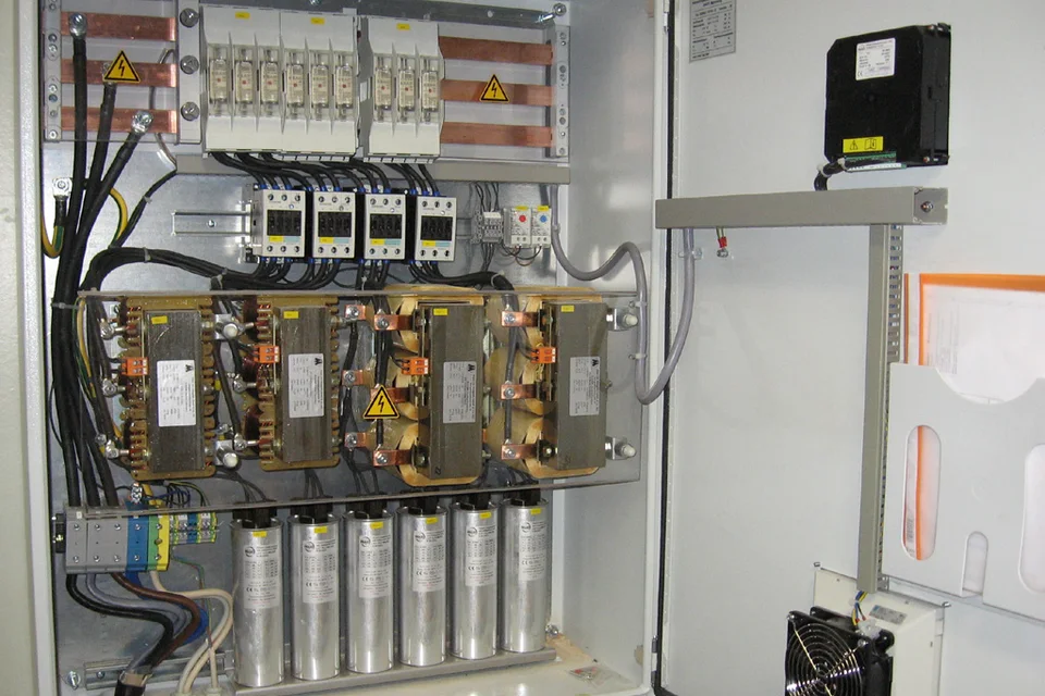
Key specifications
| System voltage | 400 V AC, three-phase |
|---|---|
| Module output at 400 V | 15 / 22.4 / 25 / 30 kvar |
| Detuning factor | 7% standard, 14% subject to project confirmation |
| Control supply | 220 V |
Product highlights
- The capacitor, detuned reactor and switch are factory matched and prewired as one compensation step.
- Each module occupies 457 × 156 × 415 mm and includes an isolating switch. A system supports up to 32 parallel groups.
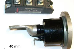
- DB-T uses zero-crossing thyristor switching. DB-H transfers steady-state current to a magnetic latching contact after turn-on.
- The capacitor has a pressure-sensitive disconnector, 60 °C built-in thermal protection and secondary protection terminals. The reactor specifies 65 °C fan start and 120 °C thermal cutoff.
- The reactor uses cold-rolled grain-oriented steel and segmented air gaps. The product brief specifies linearity at 1.8 times rated current.
- RS-485 Modbus RTU supports coordination with a SUCYC-W controller, PLC or power monitoring system.
Technical specifications
- System voltage
- 400 V AC, three-phase
- Capacitor rated voltage
- 480 V for the 400 V / 7% configuration
- Module output at 400 V
- 15 / 22.4 / 25 / 30 kvar
- Capacitor rated capacity at 480 V
- 20 / 30 / 33.5 / 40.2 kvar
- Detuning factor
- 7% standard, 14% subject to project confirmation
- Tuning frequency
- About 189 Hz at 50 Hz and 7%. Specify 60 Hz variants when ordering.
Additional specifications
- Switching response
- DB-T ≤20 ms. DB-H per hybrid-switch specification.
- Control supply
- 220 V
- Communications
- RS-485, Modbus RTU
- Dielectric withstand
- 2,500 V AC for 60 s
- Ambient temperature
- −40 to +55 °C
- Relative humidity
- ≤90% at 25 °C
- Altitude
- ≤2,000 m. Confirm options above 2,000 m.
- Dimensions (W × D × H)
- 457 × 156 × 415 mm
- Expansion
- Up to 32 parallel modules per system. Confirm controller and cabinet limits.
Model selection
Use the 400 V module output to size each compensation step. The 480 V capacitor rating identifies the internal capacitor in the order code. The table covers standard three-phase 7% configurations.
Scroll across to see all columns
| Order code | Module output at 400 V (kvar) | Capacitor rating at 480 V (kvar) | W × D × H (mm) | Switching |
|---|---|---|---|---|
| SUCYC-DB-480-20-3/7T | 15 | 20 | 457 × 156 × 415 | Thyristor |
| SUCYC-DB-480-30-3/7T | 22.4 | 30 | 457 × 156 × 415 | Thyristor |
| SUCYC-DB-480-33.5-3/7T | 25 | 33.5 | 457 × 156 × 415 | Thyristor |
| SUCYC-DB-480-40.2-3/7T | 30 | 40.2 | 457 × 156 × 415 | Thyristor |
| SUCYC-DB-480-20-3/7H | 15 | 20 | 457 × 156 × 415 | Hybrid |
| SUCYC-DB-480-30-3/7H | 22.4 | 30 | 457 × 156 × 415 | Hybrid |
| SUCYC-DB-480-33.5-3/7H | 25 | 33.5 | 457 × 156 × 415 | Hybrid |
| SUCYC-DB-480-40.2-3/7H | 30 | 40.2 | 457 × 156 × 415 | Hybrid |
Order code and options
- T · Thyristor switching
- DB-T is the faster switching option for frequently changing loads. Its stated response is ≤20 ms.
- H · Hybrid switching
- DB-H uses the latching contact to limit steady-state heating. Confirm the switching interval and response in the hybrid-switch documentation.
- Project-specific conditions
- Confirm suitability for 14% detuning, 60 Hz systems or elevations above 2,000 m before ordering. Where phase-by-phase compensation is required, review the SVG option separately.
For example, SUCYC-DB-480-33.5-3/7T denotes the DB module with a 480 V, 33.5 kvar capacitor, three-phase common compensation, 7% detuning and thyristor switching. Its output is 25 kvar at 400 V.
Application cases
- Variable-speed drives and changing loads
- For drives, injection molding or hoisting equipment, use measured harmonic and reactive power data to select the step size and switching method. Evaluate DB-T where reactive demand changes quickly.
- Rectifiers, UPS loads and significant harmonics
- Assess the measured harmonic spectrum before choosing the detuning factor. Consider an active harmonic filter where a separate harmonic-current target remains. Sites with prominent third-order harmonics may warrant review of the 14% option.
- Welding loads, flicker and cabinet retrofits
- For welding or other highly variable reactive loads, review DB-T and assess an SVG where continuous adjustment is needed. For a retrofit, confirm the existing cabinet space, cooling and busbar capacity.
Separate components or a prewired module
Separate components give the panel builder control over the capacitor, reactor, switch, controller and layout. SUCYC-DB combines the first three in one matched assembly. The controller and cabinet layout are selected for the project. The built-in isolator supports servicing at the module level subject to the approved cabinet design and service procedure.
Capacitor-bank configurations compared
For a combined system, SUCYC-DB supplies the base compensation in steps. An active branch handles the remaining harmonic current (AHF) or changing reactive demand (SVG). Coordinate the two branches in the cabinet and control design.
Scroll across to see all columns
| Consideration | Contactor-switched bank | SUCYC-DB | SUCYC-DB with AHF or SVG |
|---|---|---|---|
| Harmonic and reactive demand | Check resonance against measured network conditions. | Detuned stepped compensation. A 7% branch tunes to about 189 Hz on a 50 Hz system. | The DB provides base reactive compensation. An AHF addresses harmonic current or an SVG handles changing reactive demand, as required. |
| Response and coordination | Response depends on the contactor and switching interval. | DB-T ≤20 ms. DB-H follows the hybrid-switch specification. | Review control coordination and required active-branch response. |
| Servicing | Locate the affected capacitor-bank component. | Check whether the cabinet design allows the affected module to be isolated separately. | Assess service access and isolation for each branch. |
| Cabinet assembly | Separate components are matched and assembled at panel level. | A factory-prewired module serves as one compensation step. | Check cabinet space, heat dissipation and the controller arrangement for both branches. |
Cabinet and test details to confirm
Check the module model, system voltage, output, detuning factor and clearance against the project drawings. Request the communications map and test documentation for the selected model. Before setting acceptance criteria for impulse and inrush withstand, confirm the test waveform, duration and reference current.
Selection questions
How do I choose between 7% and 14% detuning?
Start with the measured spectrum and system frequency. A 7% reactor is the standard option and tunes to about 189 Hz on a 50 Hz system. Where the third harmonic is prominent, discuss the 14% option with engineering using the actual system measurements.
Can a single module be serviced separately?
The module includes an isolating switch. The approved cabinet design and service procedure determine whether other steps can remain in operation while a module is serviced.
Can I add compensation steps later?
The series supports up to 32 parallel groups in a system. Confirm spare cabinet space, busbar capacity and the controller’s available step outputs before planning an expansion.
When should I select DB-T or DB-H?
Evaluate DB-T where frequent switching or fast response is important. Consider DB-H for longer steady-state operation, and verify the applicable minimum switching interval in its specification.
Is a 60 Hz system supported?
Specify the 60 Hz system frequency when ordering so the tuning point and corresponding reactor configuration can be confirmed.
What controller data is available?
The module provides RS-485 Modbus RTU. Request the register map for the selected configuration and share details of the SUCYC-W controller, PLC or monitoring system you plan to use.
When should I choose a detuned module?
A detuned capacitor module combines a capacitor and reactor in one assembly. Verify its stage kVAr at the system voltage and the specified detuning factor.
Request a project quote
- System voltage and compensation capacity per step
- Switching method and existing component models
- Available installation space and wiring diagram